Impact of micro-bends and macro-bends on the optical budget of telecoms networks
The micro-bending and macro-bending of optical fibres are known problems in optical telecommunications networks because they can cause attenuation and therefore induce partial or total loss of signal. In order to provide the best quality of service and guarantee an optimised service life for the network, these two phenomena must be avoided.
Indeed, when a bending fault is present on the network, it can be difficult or even impossible to correct. In the case of macro-bending, the origin of which generally comes from incorrect installation of the cable or bare fibre, a correction may sometimes be possible, but it involves a new cost of labour and travel (e.g. another intervention on the splicing boxes). In the case of micro-bending, it is almost always irreversible. The cable will have to be replaced, which also entails new costs.
These defects, not taken into account in the basic engineering of the optical network, can be added to the other sources of attenuation inherent to optical fibres (absorption diffusion, ageing) and extrinsic to this transmission medium (splices, connectors, splitters).
This document will explain the phenomena of micro-bending and macro-bending in detail and provide recommendations to avoid and measure them.
What is macro-bending?
Macro-bending is associated with stress that may manifest itself during poor installation practices (in particular in connection or splice boxes). These are bends of optical fibres with a bend radius typically between 2 and 25 millimetres.
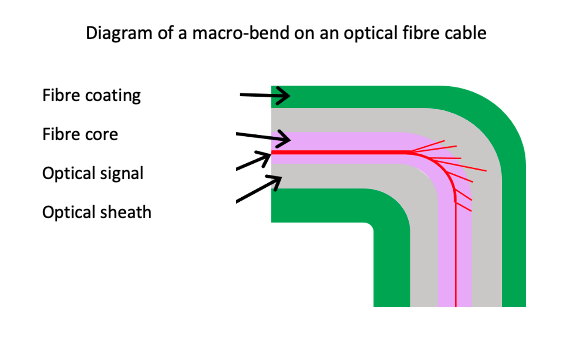
When this type of deformation is observed, part of the light guided in the core of the fibre escapes: thus, the smaller the bend radius, the greater the weakening of the signal (attenuation). Attenuation also results from the number of bends present on the fibre (i.e. the more there are, the greater the attenuation) and the wavelength (i.e. the higher it is, typically above 1,550 nm, the more sensitive the signal will be to macro-bending as it is then less concentrated in the fibre core).
Diagram of a macro-bend on an optical fibre cable
How is macro-bending induced?
Macro-bending can result from a variety of events such as:
- incorrect routing of fibres in trays;
- incorrect winding of the micro-modules in the storage areas of the boxes;
- jumper or cord routing fault in patch areas
What is micro-bending?
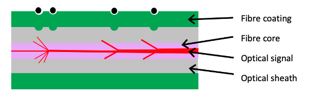
Micro-bends are less common on networks but still occur. They are associated with stress points and radial stresses (with a geometric dimension of less than 1 millimetre) distributed randomly along the fibre.
This type of deformation increases the linear attenuation of the fibre, starting with low-level wavelengths, unlike the macro-bending phenomenon. It should be noted that the attenuation related to micro-bending also increases with the increase in wavelength but less exponentially than in the case of macro-bending.
Diagram of a micro-bend on an optical fibre cable
How is micro-bending induced?
Micro-bending can result from a variety of events such as:
- the crushing of a cable segment — overhead anchor clamps tightening on the cable, compression when a vehicle or personnel passes by or a heavy object weighing down on a cable section;
- the pinching of a portion of fibre in the trays or at box outlets (cable glands);
- the compression of part of a micro- module in the overhead box guides;
- faulty fastening in the overhead boxes putting stress on the fibres;
- improper manufacture of the cable that could cause the fibres to cross, pressure from the materials or the risk of lateral contact of the fibre with other surfaces making up the cable;
- a manufacturing defect in the optical fibre (primary and secondary coatings not sufficiently protecting the optical fibre, etc.);
- a manufacturing defect in the micromodules (choice of materials, process, etc.) resulting from longitudinal compression; and
- excessive traction on the cable during installation which can thus result in contact with other elements along the cable.
How to prevent macro-bending and micro-bending?
Visual inspection
Connection, branch and splice boxes as well as cable routing must be visually inspected to detect the aforementioned faults. This check must be carried out by the installer (i.e. a self-inspection) and can be followed up by a third party seeking verification.
Assessing optical transmission
It is necessary to measure the attenuation of the optical signal using an optical time-domain reflectometer (OTDR) at two or even three different wavelengths.
By monitoring the measurements obtained using this tool and comparing the variations in attenuation between the high and low wavelengths, micro-bending and macro-bending can be detected.
Quality of the design and manufacture of optical fibre cables
Temperature variations cause differential shrinkage and expansion of the various materials making up the optical cable. These differences in the behaviour of materials can lead to stress on the fibres which causes operational losses via micro-bending or macro-bending. Perfect control of the design and manufacture of fibres and optical cables combined with appropriate use of these products are essential to avoid these phenomena. An optical cable for telecoms applications is a technical product and must be designed to withstand the environmental stresses associated with its field of use.
The essential elements for a cable that is perfectly adapted and resistant to its environment include:
- proper control of the extrusion processes for raw materials used (plastic materials, reinforcement elements, etc.);
- industrial processes for manufacturing and assembling the components of the cable; and
- a suitable choice for the type of fibre used.
Training of field staff
To sustain the optical network, it is important to choose quality training for field staff. Compliance with implementation rules and best practices regarding installation and connection is essential!
Sensitivity to bending and the need for densification of optical networks
Great care must be taken when it comes to the tendency of fibres to bend. The choice of optical fibres belonging to the “reduced sensitivity to bending” families is a key success factor (see ITU G 657 A1 or A2). The use of this type of fibre combined with the design of high-tech cables makes the cables and optical infrastructures more compact in order to meet the challenges of FTTx networks. These optical fibre families are now standardised and widely available. They meet the new challenges associated with the densification of networks.
As uses and technologies evolve, we are seeing a considerable increase in the amount of data exchanged.
High-density fibre cables are an ideal solution for optimising optical infrastructures, making them profitable and meeting the need for densification (increase in network capacity, optimisation of deployment costs). To find out more, read our article on the densification of optical networks.
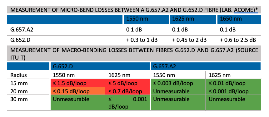
Tables of micro-bending and macro-bending loss measurements :
Compliance with standards regarding bending phenomena
To avoid micro-bending and macro-bending, compliance with existing standards applicable to the environment to which products are subject (fibres, cables, passive components) must be taken into consideration. These phenomena are governed by international standards specifying the quality of optical fibres with respect to macro-bending and the segmentation into “product families” (EN IEC 60793-2-50) as well as the means and methods for measuring these phenomena. For macro-bending, the standard is IEC60793-1-47. For micro-bending, the standard is IEC TR-62221.